Because both film and video are actually "multi-media" formats, we as motion picture professionals must understand the association of audio as it applies to the visual format being employed. Though audio and sound is principally the responsibility of the Recordist or Location Mixer, the video operator must also possess an extensive knowledge of film and video related audio.
When we film or video record a live action scene, an audio track is typically recorded at the same time. Later in post production, this track may be altered, shifted, remixed or even replaced, "looped".
Since some video systems do not run exactly at the same speed as some film systems, there is the potential for slight alterations of the film and sound sync. For this reason the video playback operator must utilize a variety of techniques to allow the post production team to properly sync the sound to the picture.
What ever technique is employed, it is the responsibility of the Sound Recordist and the Video Playback Operator to insure the availability of properly recorded sound during the film production process. Each film element must be capable of being associated with its own properly "in sync" and recorded high quality track.
There is much confusion in the use of terminology associated with the levels associated with audio and sound. Here is a brief discussion as it applies to the art of motion picture and video sound.
DB in Audio
The DB or decibel is a RELATIVE measurement of audio.
You can hear sound, but you cannot hear audio. Audio refers to the electrical signal employed to transmit sound over wires, in a wireless fashion such as over radio waves, or to recorded either in analog or digital form.
Sometimes DB and VU are used interchangeably. If an audio level changes from one level to another, that change can be described in DB. Particularly, if an audio level electrically is doubled, we say it is 6 DB higher.
DB in Sound
Sound is defined as a variable pressure of air that can be detected by the human ear or a microphone.
DB in sound is an ABSOLUTE measurement that can be calculated based on the pressure it applies at a particular location of the measurement.
DBm
DBm is an ABSOLUTE electrical measurement used for audio. Zero DBm is not zero audio signal. Zero DBm is actually the base reference for all audio measurements.
Typically line level is between -10 to +10 dbm. Normally +4 dbm.
Balanced Line is an electronic term given to an audio signal and refers to the manner of which the audio signal is transmitted over wires. A minimum of two wires are required for balanced audio circuits. Three wires are typical, where the third is the ground or shield. It is not possible to have a balanced line on a two conductor circuit if one of the wires is the shield or is grounded. There is a 5 conductor manner of running balanced lines but there is no standard to this configuration.
The balanced audio circuit carries the audio on one wire and its compliment on another wire. When the balanced audio is received by a transformer or an active differential amplifier, only the difference between the two signals is detected as audio. Signals present on both wires are canceled. Due to various environmental issues, undesirable noise, interference or hum may be picked up by an audio cable. In a properly balanced audio cable, such interference will infect both signal wires equally and will therefore be canceled by the balanced line input.
Balancing the audio line is one of the principal techniques that makes all professional audio systems possible. It is the balanced line audio technique that makes it possible to speak on a telephone over a twisted and unshielded pair of conductors for many miles while it is sometimes difficult to get a noise free signal on an unbalanced line more than a few feet, such as on a home stereo system
Next are some illustrations of typical ways that we balance
and unbalance audio. I have listed both solid state methods and passive
methods.

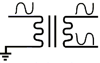
The left side of the transformer is the input. With one
side grounded, the transformer will yield us two outputs. Both are completely
isolated from the input and one is the inversion, 180 degrees out of phase,
of the other. This is also referred to a balanced or differential line
driver.

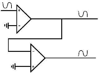
Another way to create a balanced line is to use op-amps.
Using two unity gain amplifiers, one can create a true compliment, inversion
or 180 degree (out of phase) signal from the input. Again the input is
shown on the left and the two outputs on the right.

This passive or transformer line receiver will create
an output (on the right) that is the difference of the two signals that
are applied to the transformer input (on the left). We only get an output
when the signals on the two input terminals are different.

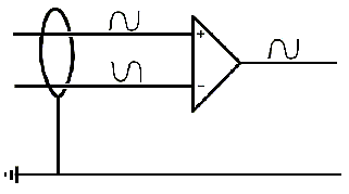
Just as the passive or transformer line receiver will differentiate its inputs giving us an output that is representative of the differential input, the active balanced line receiver made of an Op-Amp will give us sum of the inputs. Again, input on the left, output on the right.
In this illustration, I have shown the shield or ground.
The active component of the Op-Amp will have some ground reference as it
is operated from a power supply. That same ground is the reference by which
the Op-Amp output will be measured.

This illustration is the same as the balanced Op-Amp line
receiver shown above. In addition to the differentiating of the input signals,
the common mode rejection capabilities of the balanced line receiver will
cancel noise. The ragged line that is illustrated on the ground and the
two input lines (on the left of the Op-Amp), is the symbol for noise. We
presume that noise will be collected on the input lines to an equal degree
and therefore be in phase on both input terminals. The balanced line receiver,
either active (shown) or passive, (the transformer), will cancel the noise
and only give us an output that contains our audio.
Since all professional audio cables are also shielded, the shield will minimize the level of any interference that may be available to infect the audio path.
On professional audio cables, the shield is never used as a return signal path. It is only used to equalize grounds or commons, and to drain off noise and interference to keep it from infecting the audio signal.
On some occasions a difference of ground potentials between two pieces of audio equipment will require the lifting of a ground form one end of a cable or the other. This is because highly different ground potentials can cause such current to be carried by the shield that it may present interference greater than the differential input can reject. Such interference is called a "ground loop".
|
|
|
|
|
|
|
|
|
|
|
|
Nagra refers to balanced line output as isolated output. The isolated output on the Nagra is available on two banana plugs on the side of the unit. The third banana plug is ground.
It is possible to balance an unbalanced line with the use of an audio transformer. Most balanced lines are 600 ohm lines so the typical balancing transformer is a 600 to 600 ohm type.
If you are being furnished a balanced line, the best way to receive it is to use a balanced input of matching ohms. If only unbalanced inputs are available, use a transformer to unbalance the line.
Canon Plug - The brand name of a particular type of XLR connector. Though used by some generically to refer to such XLR connectors, the term is a brand name only.
XLR-3 (P or M) - The type of connector used world wide for the interconnection of professional audio equipment using balanced line principals. However, using an XLR connector by no way indicates whether an audio circuit is balanced or unbalanced, line or microphone level. It is professional audio standard for audio outputs to be present on XLR-3P (male) connectors and that audio inputs be XLR-3F (female). But for every rule there are many exceptions. Be flexible.
RCA Plug - An Unbalanced line level connector. A transformer must be used to connect an audio feed on an RCA plug to Balanced Equipment.
Speaker Level - A output that is designed to drive speakers or headphones. Not to be used for the interconnection of audio equipment.
Most video playback operations will require the feeding of audio either during the playback or at some other time as a guide reference.
VIDEO IMAGE "STAND ALONE" playback units provide several locations for the connection of audio feeds for playback.
1. Balanced line level (XLR-3P) connector on the back of the audio switcher.
2. Unbalanced line level (RCA-F) connector on the back of the audio switcher.
3. Individual line level (RCA-F) connectors on the back of the individual playback VCRs.
4. Monitor line level output (PIN-F) connector on the back of the individual playback VCRs.
In most cases ...#1 above will satisfy the audio requirements. For a local monitor for the video operator, we use either headphones on the recorder, or use a MIKROMONITOR 1 (a self amplified audio monitor), with an (XLR-3P) to (RCA-M) adapter cable attached to the unbalanced audio output on the rear of the audio switcher.
The (XLR-3P) connector, on the rear of the audio switcher, is specifically designed to interface with the largest amount of audio equipment one may find with any Sound Mixer. This audio output is a transformer isolated 600 ohm line level output. Normal audio cable should be used for the interconnection. All Video Playback operators should have at lease one audio cable of at least 50 ft. with your equipment. The requirement for any additional cable should be handled by the Sound Person.
|
|
|
|
|
|
|
|
|
|
|
|
|
|
|
|
|
|
|
|
|
|
|
|
A standalone audio monitor such as a MIKROMONITOR I can be used for a sound feed to the set during playback. If the Video Playback Operator does do sound playback during the video feed, the Sound Person will probably ask that it be only used during rehearsal and not allowed to contaminate the audio track during an actual take.
Video Playback personnel should attempt to provide an audio feed to the Sound Person of the entire track for each video piece used during your day of playback.
This section deals with the recording of an audio feed in each of two situations.
1. When the location mixer is providing the feed.
2. When there is no location mixer at all.
Taking a sound feed for recording when the location mixer is providing the feed is the typical manner of getting audio on the video tape. Video tape audio is generally not considered the production track for even the video material. It is important that the Location Mixer provide a 1/4 inch recording of all video recorded. If it is impossible to make a 1/4 recording during the video recording, it will undoubtedly need to be done later. We can make such a recording from the 3/4 inch video tape to 1/4 inch audio tape at Video Image at any time after the original video tape is generated.
The Location Mixer will probably give you a feed from one of the following sources available on his mixer or Nagra. Following each location description, we indicate some pros and cons for each location.
a. Line Level Output from the Mixing Console.
This is perhaps the best location for taking a feed from the location mixer. It is unaffected by the NAGRA, is completely isolated and is usually balanced. Audio outputs are typically on an XLR-3P (male connector). Some audio equipment may have such line level output on other connectors, they should be considered exceptional rather that the rule. Connector sex turnaround should never be a problem for either the Location Mixer or the Video Operator.
b. Isolated Output from the NAGRA.
This output is on banana plugs. There is no provision for grounding the shield of the cable being fed from the isolated line outputs from the NAGRA.
c. Headphone or Monitor Output.
Sometimes it is necessary to take your feed from the Headphone or monitor output. Use this as only a last resort. This is not a high quality audio output and is subject to level changes made to the monitor circuit. The monitor circuit is intended to drive headphones and is unbalanced and not impedance matched for normal audio line use. If you must use the monitor circuit, it may be necessary to use a transformer at the source end to prevent interference and noise from getting in the Production Audio or on the Video Audio.
SETTING THE LEVEL
After establishing the audio feed connection, ask the Location Mixer to give you a tone. This tone may be at -8 VU or -8db or at 0 VU or 0db. Whatever the case, set the level on the video recorders for the same position as indicated on the Location Mixers meter. Once set, several seconds, at lease 30, of the tone should be recorded with Color Bars for reference and playback setup later. After the meters are calibrated as above, it should not be necessary to make any further adjustments to the Video Recorders input level controls. Always monitor the Video Recorder with headphones for audio quality and discuss any difficulties with the Location Mixer. All audio quality is the responsibility of the Location Mixer, he will be interested in insuring that the audio on the video tape is of the highest quality.
Be sure that all audio limiters on the video recorders are turned off as the level is being adjusted by the location mixer.
When there is no Location Mixer, the only feed that can be recorded is from a microphone that you provide. There is a microphone input on the front of the Video Tape recorder. The person in charge of the production must be informed that recording sound in this fashion is not considered appropriate for a Production Track. The Microphone input on the Video Tape Recorder is unbalanced and a source for hum and noise on the audio track. If high quality audio is needed, a microphone Mixing Console should be used, and a qualified Recordist should be watching and adjusting the audio level at all times.